
6 6
PLUMBING CONNECTION
SPRING 2015
It is effectively the same as the
dimensionless pump type factor “K”
in the test code standards, except “K”
uses cubic metres per second as the
flow unit.
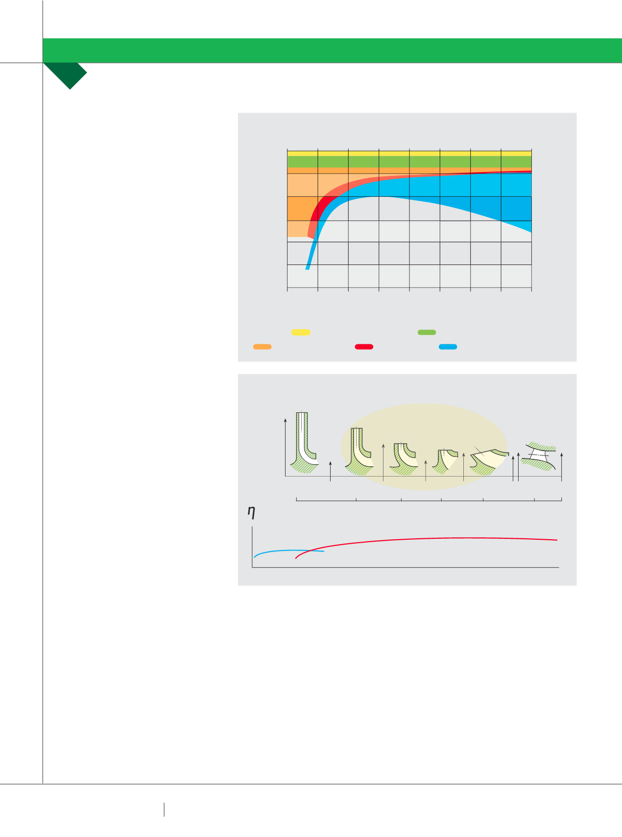
Legendary pump designer, A.J.
Stepanoff created this chart outlining
the various components of pump
inefficiency and showed how these
vary with specific speed (Fig 3).
From Stepanoff’s chart you can see
that casing Hydraulic Losses and Disk
Friction vary significantly with changes
in Specific Speed. In these metric units
the best impeller efficiency is around
Ns of 3000.
As we saw from Fig 1, low Ns
impellers are larger diameter, narrow
radial flow units. Higher values of Ns
relate to fatter more open shaped
impellers. This makes perfect sense
because the fatter, more open shaped
impellers will have less disk friction
as a percentage of the hydraulic work
being done by the impeller.
The bottom line is that narrow
impellers are less efficient than
“fatter” shaped impellers. See Fig 4.
Bearing the above in mind, it makes
sense to aim for the best shape
impeller when considering what type of
pump to select. If you arbitrarily dictate
the maximum running speed you may
force the pump selection into a low
Ns shape and this will mean a more
expensive and less efficient pump.
Consider the following pump
selections for the same duty but
different speeds (Fig 5):
This is a tangible example of how
specifying a maximum running speed
of 1500 rpm will in this instance cost
the end user dearly; not only in capital
cost but in total cost of ownership.
Now some of you may be grumbling
about reliability, noise and vibration
being also important. Yes they are, but
look at the size of the casing on the
slower running unit, look at how much
heavier its impeller must be and look
at the greater surface area available
to transmit hydraulic noise. In a later
discussion I will look at these aspects
PUMP SCHOOL
RON ASTALL
in more detail and show how the faster
running pump can indeed be more
reliable and can be potentially quieter.
SOWHAT RUNNING SPEED SHOULD
YOU SPECIFY?
You should not specify the running
speed at all!
A great window on this process is the
pump vendor’s range chart. A simple
suggestion is to always start with the
highest speed range chart. If this does
not bear fruit, look at the next speed
down. If there is a sensible selection
at a higher speed it is almost certainly
going to be a more efficient pump than
a lower rpm unit doing the same duty.
To illustrate this, in Fig 6 below I have
overlaid a 2980 rpm range chart (in red
outline) over a 1470rpm range chart for
the same manufacturer. Below the red
outline you can see the regions where a
1470 rpm pump is going to be a better
selection. Inside the red outline, a 2980
selection ought to be better.
Select on the basis of the hydraulic
duty and specify your other primary
requirements directly; such as noise
FIG 3: TYPICAL CENTRIFUGAL PUMP POWER LOSSES
FIG 4: IMPELLER SHAPES AND EMISSIONS
POWER % OF NORMAL INPUT
SPECIFIC SPEED m
3
/h, m, rpm
LOSSES % OF NORMAL INPUT POWER
100
0
95
5
90
10
85
15
80
20
75
25
70
30
0 1000 2000 3000 4000 5000
PARTIAL
EMISSION
EXPECTED BEST EFFICIENCY
SPECIFIC SPEED
FULL EMISSION & AXIAL FLOW
6000 7000 8000
MECHANICAL LOSSES 1%
IMPELLER LOSSES 2.25%
DISK FRICTION LOSS
LEAKAGE LOSS
CASING HYDRAULIC LOSSES
500
15,000
1,000
2,000
3,000
5,000
10,000
SPECIFICSPEED
RADIALTYPE
FRANCISTYPE
PROPELLERTYPE
MIXEDFLOWTYPE
RADIALFLOW
AXIALFLOW
“BEST” SHAPE IMPELLERS


