


 52 / 116

5 2
PLUMBING CONNECTION
WINTER 2016
TANK FILLING VALVES IN BUILDING
RESERVOIR APPLICATIONS
F
or too long most installers see the standard servo
type level control valve (modulating horizontal float
style) as the answer to all level control installations.
While these types of valve do serve a purpose, they are
simply limited to an always full tank filling situation where
incoming pressures are low and head loss across the valve
is minimal.
In this article we’ll address tank filling valves that are
known as self-acting hydraulically actuated diaphragm
control valves and direct acting mechanical valves. These
valves require only the pressure of the incoming supply
pressure to control water levels and are not reliant on
external controls to operate.
FLOWS
It’s important to understand the requirements of water
authorities’ minimum pressures offerings as this sometimes
dictates the size of the valve that can be used. Size a valve
too small and you may run the risk of not being able to
meet the flow demand when pressures are at their lowest.
A good knowledge of the pressures to be experienced will
help the valve manufacturer size the correct valve. Fire and
domestic water supply requirements often differ between
states and as always codes for both fire domestic water
applications should be followed.
PRESSURES
Taking the above into consideration, it is always right
to know the incoming pressures to be experienced during
normal operations of the Tank Filling Valves (TFV). Most
incoming pressures are reasonably high and installing valves
directly at or near the outlets of pipework to the tank may
cause the valve to experience severe cavitations due to high
change in pressure (∆P) across the valve. Cavitations can
be caused by either high or low flows with high ∆P. In this
instance it would be advisable to install a pressure reduction
valve upstream of the TFV so as to negate the effect it has
on the TFV. The pressure reduction valve will impede on the
flow requirements as they modulate to accommodate flows
regardless of differing upstream pressure fluctuations.
VALVE LOCATIONS
While most servo type direct acting float valves get
installed at the outlet of the pipework and generally in
the tank, modulating self-acting hydraulically actuated
diaphragm control valves should be installed external to the
tank with control pilots either within or external to the tank.
Preferably the valves should be installed in the horizontal
upright position at the base of the tank’s inlet pipework.
They can operate in the vertical ascending position as well.
Locating the TFV and control piloting external to the tanks
would be the best option where possible as this will prevent
future issues in regards to servicing and replacement. If
the control valve and piloting are external to the tank this
will also negate the safety requirements of entering tanks
during and post construction.
VALVES SELECTION V APPLICATION
DOMESTIC FEED RESERVOIRS
When considering valves for this application, there are two
common types of control: valves with bi level or modulating
level control. They can either be in altitude pilot or float
WHILE MANY BELIEVE THAT SIMPLY INSTALLING A LEVEL CONTROL VALVE IN A RESERVOIR BUILDING APPLICATION
WOULD BE A SIMPLE PROCESS, TOO OFTEN THIS IS NOT THE CASE. IN HIS NEW COLUMN,
RUSS DUNNE
OF BERMAD
WATER TECHNOLOGIES EXPLAINS WHAT ELSE THERE IS TO KNOW.
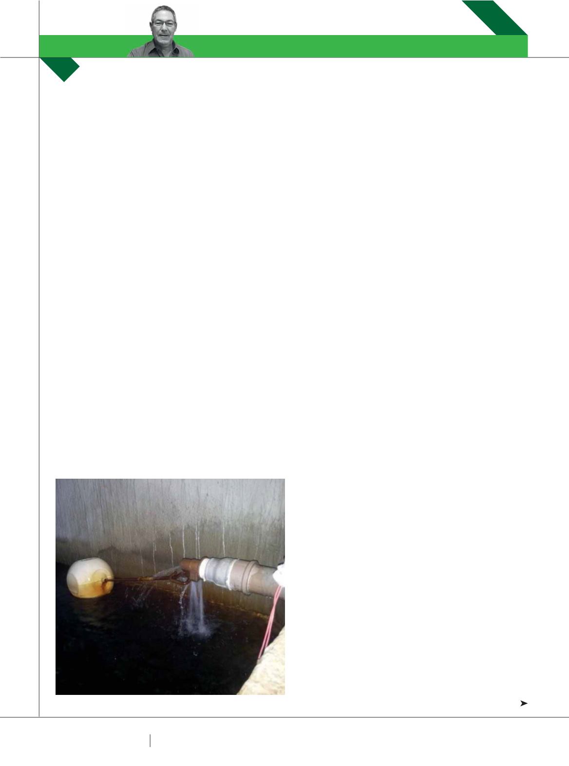
The above is a typical installation of mechanical float valves.
VALVE CONTROL
RUSS DUNNE