


 34 / 116

3 4
PLUMBING CONNECTION
WINTER 2016
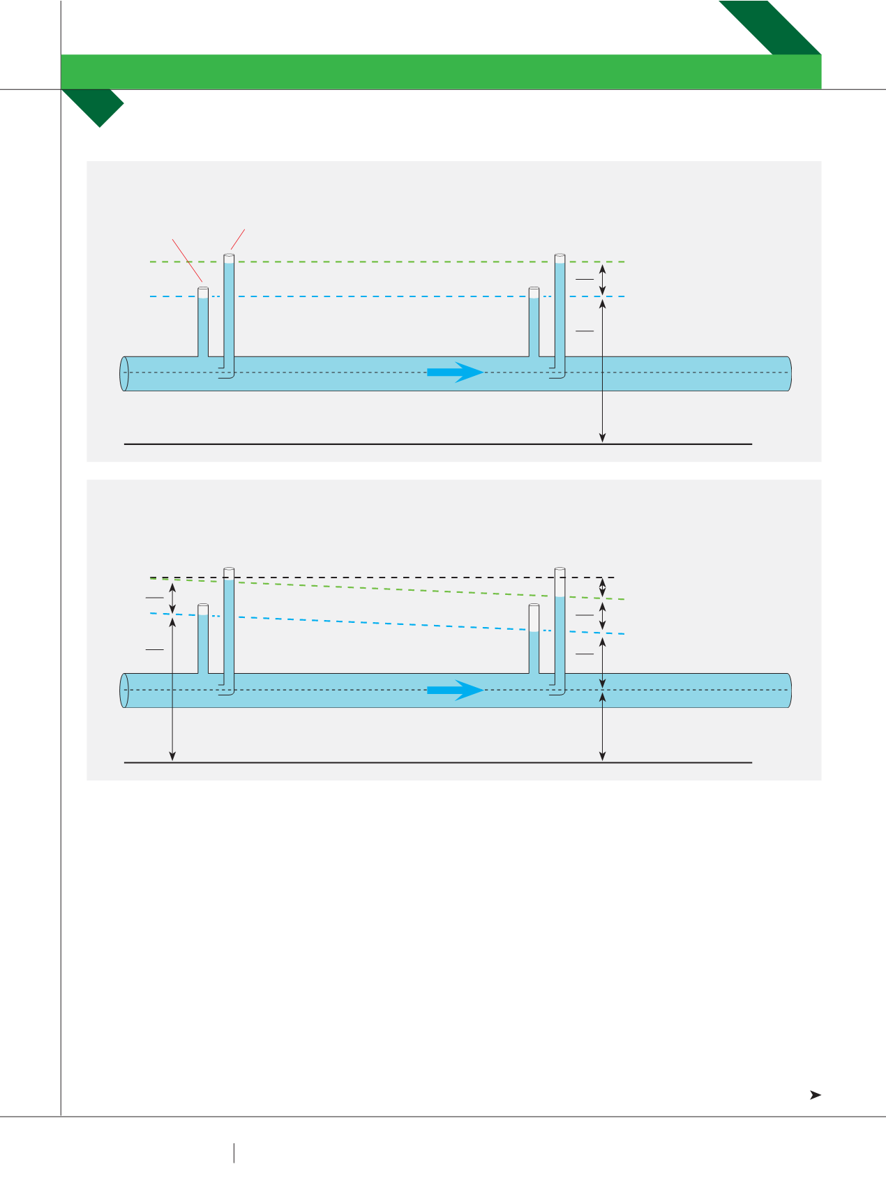
the Pressure Head and the Velocity Head as shown in Figure
2. Please note that the pipe shown in Figure 2 is an “ideal
pipe” which means there are no losses shown in this system
(this is impossible in real systems).
FRICTION LOSSES
In real pipe systems, fluids lose energy as they move
through the pipes. This energy loss (or pressure loss) is
caused by a variety of reasons including friction, turbulence
through fittings, change of flow direction, heat and noise.
When designing common pipe systems, we are usually
concerned with two main pressure losses: Friction Losses
and Form Losses.
Friction Losses, as the name implies, are caused by
friction that is generated between the fluid and the pipe (or
channel) walls due to the fluid’s viscosity. While pipes may
look and feel smooth, at a microscopic scale pipe walls are
actually quite rough and they generate a lot of turbulence
and friction in the flow. In order to overcome these frictional
forces along the walls, the fluid loses significant pressure
energy as it moves through the pipe system.
Friction losses are often referred to as “Major Losses”
as they generally account for the majority of losses in a
typical pipework system. Major losses (usually expressed
as H
f
) for a steady flowrate, in a straight pipe of constant
cross-sectional area are generally quite straightforward
to calculate. H
f
is usually expressed as a certain value of
pressure (or head) loss per metre, i.e. a set proportion of the
total flow energy is lost along every metre of pipe. Figure 3
shows how friction losses (H
f
) reduce both the HGL and the
EGL in a straight pipe between points (1) upstream and (2)
downstream.
HYDRAULIC CLASSROOM
DR TERRY LUCKE
FIGURE 2 – HGL AND EGL IN AN IDEAL PIPE SYSTEM
PIEZOMETER
PITOT TUBE
VELOCITY HEAD (m)
PRESSURE HEAD (m)
POTENTIAL HEAD (m)
DATUM
ENERGY GRADE LINE (EGL)
HYDRAULIC GRADE LINE (HGL)
V
2
2
g
V
pg
Z
FIGURE 3 – HGL AND EGL IN A REAL PIPE SYSTEM INCLUDING FRICTION LOSS
VELOCITY HEAD (m)
LOSS (m)
PRESSURE HEAD (m)
POTENTIAL HEAD (m)
DATUM
ENERGY GRADE LINE (EGL)
HYDRAULIC GRADE LINE (HGL)
V
2
2
g
H
f
V
2
2
g
P
pg
P
pg
Z
Z
(1)
(2)
X