


 38 / 116

3 8
PLUMBING CONNECTION
WINTER 2016
FORM LOSSES
The other type of pressure losses in pipe systems are
Form Losses. These are often referred to as Minor Losses
because in a typical system, these losses are usually much
less than friction (Major) losses. Form Losses are caused
by the excessive turbulence generated in the fluid when it
has to travel through pipe fittings and other components.
For example, when a fluid has to travel through a valve, or
around a bend, this causes significant turbulence which
makes it more difficult for the fluid to flow. This results in the
fluid losing pressure (energy).
Fittings and components that cause pressure losses in
pipework are generally allocated a form loss coefficient
designated as a K factor (Table 1). To estimate the pressure
loss (H
L
) due to a component or fitting, the K factor is also
simply applied to the velocity head as shown in Equation 2.
EQUATION 2
where:
H
L
= Minor (form) loss (m)
K = Form loss factor (dimensionless)
V = average pipe flow velocity (m/s)
g = gravitational force on earth (9.81m/s2)
Example 2
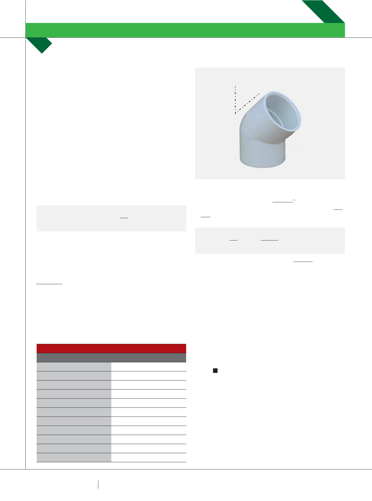
Calculate the headloss (m) through the Ø80mm, 45° PVC
bend shown in Figure 4 when the flowrate (Q) is 15 L/s. The K
factor for the bend is 0.3.
Solution:
∫ First we need to calculate the velocity in the pipe (V =
Q/A).
TABLE 1 – TYPICAL K FACTORS OF COMMON VALVE AND FITTINGS
Valve or Fitting
K factor
Globe Valve – Wide open
10
Globe Valve – ½ open
12.5
Gate Valve – Wide Open
0.2
Gate Valve – ¾ Open
0.9
Gate Valve – ½ Open
4.5
Gate Valve – ¼ Open
24
Return bend
2.2
Standard Tee
1.8
45° elbow
0.3
90° elbow
0.9
Ball check valve
4.0
∫ Area =
ʌ
D
2
/4 =
ʌ
x 0.08
2
/ 4 = 0.005 m
2
∫ V = Q/A: Velocity = Q (0.015 m
3
/s) / Area (0.005 m
2
) = 3.0
m/s
∫ Now insert values into Eq. 2:
So the minor head loss in the elbow = 0.138m (ans).
To calculate the total pressure losses in a pipe system, we
simply go through and sum the individual Major and Minor
losses in each section. As long as the total pressure driving
the system is greater than the total losses, we have flow.
If not, we need to either increase system pressure (bigger
pump or potential head), reduce Major and Minor losses
(better design or larger pipes), or a combination of both.
I hope this article has helped to improve your
understanding of pressure losses in pipe systems due to
friction and form losses. I have purposely tried to simplify
the article as much as possible to make it easier to
understand. The underlying fluid mechanics principles are
obviously a bit more complicated than this, but not that
much.
Please feel free to email me any comments, questions or
suggestions at
tlucke@usc.edu.au.
Contact:
Dr Terry Lucke
Associate Professor in Hydraulic and Civil Engineering
School of Science and Engineering
University of the Sunshine Coast
Building H1.Room 2.48
QLD 4558 Australia
Email:
tlucke@usc.edu.auHYDRAULIC CLASSROOM
DR TERRY LUCKE
H
L
K
=
V
2
2g
H
L
K
=
V
2
2g
0.3
0.138 m (138mm)
=
=
3.0
2
2*9.81
FIGURE 4 – Ø80MM, 45° PVC BEND
Ø80mm
45º