


 32 / 116

3 2
PLUMBING CONNECTION
WINTER 2016
PIPE SYSTEM LOSSES
I
n the last edition I discussed the fundamentals of
pressure and related it back to pipe system design using
some everyday examples. You may remember I used
the term “maximum theoretical pressure” in some of my
examples in the last article because there are a number of
other factors that will cause pressure losses in pipework
systems such as pipe friction and form losses.
Pipe system pressure losses are very important and they
can significantly affect expected pipework flowrates and
velocities, as well as system performance.
In this issue I will provide a simple explanation of some of
the fundamental causes of pressure losses in fluid systems.
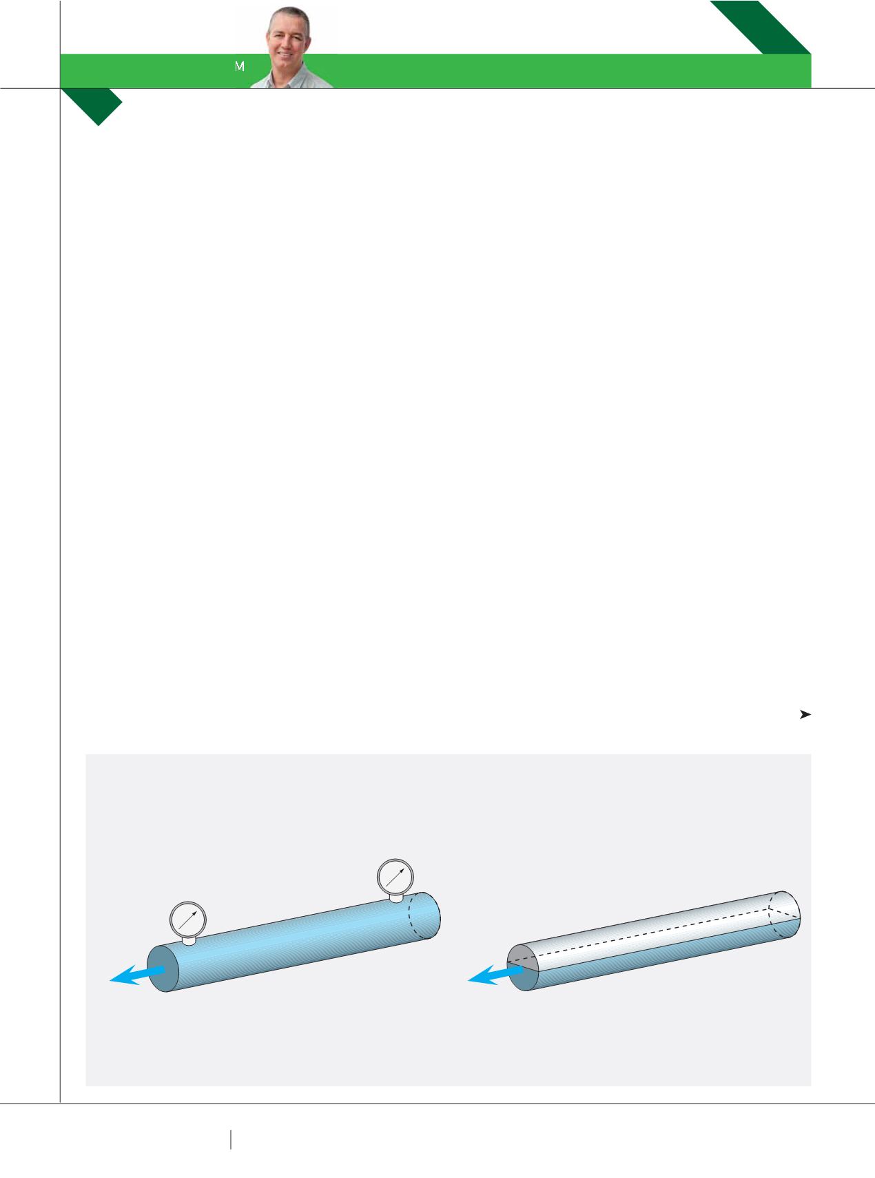
There are generally two types of pipe flow: pressurised
pipe flow (i.e. water supply systems - Fig. 1a) and open
channel pipe flow (e.g. stormwater drainage pipes - Fig. 1b).
The difference between pressurised pipe flow and
open-channel flow is in the fundamental mechanism that
drives the flow. For open-channel flow, gravity is the only
driving force acting on the fluid, i.e. water flows downhill.
However, for the flow in pressurised (full-pipe) systems,
while gravity may also play a role, the main driving force
is likely to be a pressure gradient along the pipe (i.e. the
fluid can flow uphill in a pressurised full-pipe system). For
example, in Figure 1a, when the pressure at point (1) is
greater than the pressure at point (2), a positive pressure
gradient exists which drives the fluid along the pipe from
point (1) to point (2). Importantly, if the pipe is not full
(Fig. 1b), it is not possible to maintain this pressure
difference (P1= P2) so the fluid does not flow (unless it is
affected by gravity).
Before we get into pipe pressure losses, I think it is a good
time to explain the concepts of hydraulic grade line (HGL)
and energy grade line (EGL). The HGL is a line that can be
drawn along a pipe to indicate the elevation to which the
fluid would rise if open to atmospheric pressure. This is
shown in by the piezometer tubes in Figure 2. It is also the
same height that the fountain of water would theoretically
raise if you punched a hole in the top of the pipe.
The HGL is an indicator of static pressure and is not
affected by the velocity of the fluid. The HGL is also often
called the Pressure Head and the units are usually measured
in metres height of fluid (m). In an open-channel, or a
partially full pipe, the HGL follows the water surface. The HGL
is the most important indicator for designers of stormwater
drainage systems because it indicates the water surface
levels (and potential overflows) in any of the system
components open to the atmosphere (i.e. in gutters or
drainage pits). It also identifies locations of any potentially
excessive system pressures.
The energy grade line (EGL) is a line that can be drawn
along a pipe indicating the total energy at any point in the
pipe. The EGL values generally include the Potential Head,
DR TERRY LUCKE
EXPLAINS PIPE SYSTEM LOSSES, THE REASONS WHY THEY OCCUR AND HOW TO AVOID THEM.
FIGURE 1 – DIFFERENT PIPE FLOWS
HYDRAULIC CLASSROOM
DR TERRY LUCKE
(A)
PRESSURISED PIPE FLOW
(2)
(B)
OPEN-CHANNEL PIPE FLOW
P
2
≠ P
1
Q
(1)
P
1
= P
2
(2)
(1)
Q