


 62 / 116

6 2
PLUMBING CONNECTION
AUTUMN 2015
Single stage pumps with hydraulically unbalanced
impellers will experience higher axial thrusts at low flow, as
will multistage pumps without a balancing device; such as
vertical turbine pumps. Hydraulically balanced designs are
theoretically unaffected.
A less predictable aspect, however, is the problem of axial
shuttling that may sometimes occurs due to recirculation
and flow reversals at low flow. Significant axial shuttling will
not only load up the thrust bearings but will also play havoc
with mechanical seal reliability.
RADIAL THRUST – VOLUTE CASINGS
All the flow path geometries in the pump are
designed for BEP velocities. When a pump is operated
away from BEP, the velocity profile is distorted. At low flow,
the impeller is still trying to push out the liquid at design
velocities but as flow progresses around the volute the
velocity profile must slow down to match the outlet flow.
This results in a higher pressure distribution towards the
exit and hence a higher average pressure in this region
of the casing. This acts on the periphery of the impeller and
creates a radial (side) thrust which is, of course transmitted
via the impeller to the shaft and bearings. See Fig 4.
This side loading on the shaft can be quite severe and
has even been known to lead to shaft breakage in lighter
construction pumps as well as considerable reduced bearing
life. Some “Heavy Duty” pump standards such as API 610
specify minimum bearing life to be calculated at zero flow as
well as at rated flow for this reason.
Pumps with double or staggered volutes are often used
to minimise this effect. A double volute pump casing can
reduce this radial loading to around a quarter of that of an
equivalent single volute.
If low flow operation is expected to be a regular feature of
a particular application, it would be wise to request bearing
life calculations at the low flow duty and where practical,
seek out double volute construction along with a heavy duty
shaft and bearing arrangements.
TEMPERATURE RISE
An 80% efficient pump turns 80% of the input shaft power
into useful flow and pressure. What happens to the other
20%? This 20% energy loss basically goes into heating the
pumped liquid. Indeed, there are metering devices available
that accurately measure the fluid temperature difference
between the pump inlet and outlet to determine pump
efficiency from the temperature rise.
Efficiency reduces dramatically at low flow. Consider a ten
kilowatt pump operating with an efficiency of 30%. In reality,
this is a three kilowatt pump and a seven kilowatt heater.
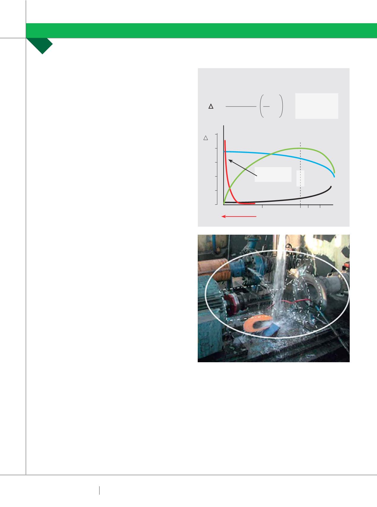
The formula for calculating temperature rise across a pump
is very simple. See Fig 5.
If you are on the ball, you will have spotted that “n” in the
Delta T formula is pump efficiency which is of course zero
at zero flow. If you are even a passable mathematician, you
will also have worked out that one divided by zero is equal to
infinity. Yes, the theoretical temperature rise in a pump at
zero flow is infinite!
Yes, this is scary and yes the reality is that pumps get very
hot very quickly at zero flow. See Fig 6.
OK, in a single stage pump it is unlikely that you will
PUMP SCHOOL
RON ASTALL
FIG 5: LOW FLOW TEMPERATURE RISE
HEAD
EFFICIENCY
LOW FLOW RATES
POWER
BEP
TEMPERATURE
RISE CURVE
50%
H
100 110 125
Q%
T
T =
g X H
1000 X C
P
- 1
1
n
T (˚K)
g = 9.8 M/s2
H (m)
Cp (kJ/kgK)
(Cp FOR WATER = 4.18)
N = DECIMAL EFFICIENCY
FIG 6
THE EXPLODING PUMP:
This process water pump was
operating with both suction and outlet valves closed. The
water contained within the pump casing superheated and
the high pressure steam caused the pump to explode.