


 58 / 116

5 8
PLUMBING CONNECTION
AUTUMN 2015
A
sk 10 different pump engineers for their guidelines on
establishing centrifugal pump minimum flow and you
might get ten different answers. Even agreeing on a
basic definition for minimum flow can be problematic.
A definition that at first glance seems more than
reasonable is as follows: The lowest pump flow that can be
maintained continuously without sustaining damage.
So if I always operate my pump above this “minimum
flow” my pump will never wear out, right? Wrong. Pumps
can wear out even if operated at Best Efficiency Point (BEP).
So we have to assume that we are talking about avoiding
accelerated wear. What rate of wear is acceptable? Is it
based on bearing life considerations or is internal erosion
also considered? Where do we draw the line and who decides
on the criteria? Should it be based on vibration criteria?
The American Petroleum Institute Standard API 610 for
the oil and gas industries uses vibration criteria to define
“minimum continuous stable flow” as the lowest flow at
which the pump can operate without exceeding the vibration
limits imposed by this International Standard. This is not a
bad definition because a vibration criterion implies a certain
level of internal havoc within the pump and if we stay away
from bad vibration, the pump must be ok. Sounds good, but
there are a number of pumps that remain externally smooth
at very low flows; even down to zero flow, without exceeding
the API 610 vibration limits. Thus the vibration approach is
not useful in all instances.
What about temperature rise? For some pumps such
as multistage units or when handling liquids that easily
vaporise, temperature rise at low flows may also impose
limits. This can be a particular issue in multistage pumps
that use balance disks or similar devices to control axial
thrust; where the liquid temperature rise may be sufficient
to cause vaporisation when bled back to lower pressure
regions.
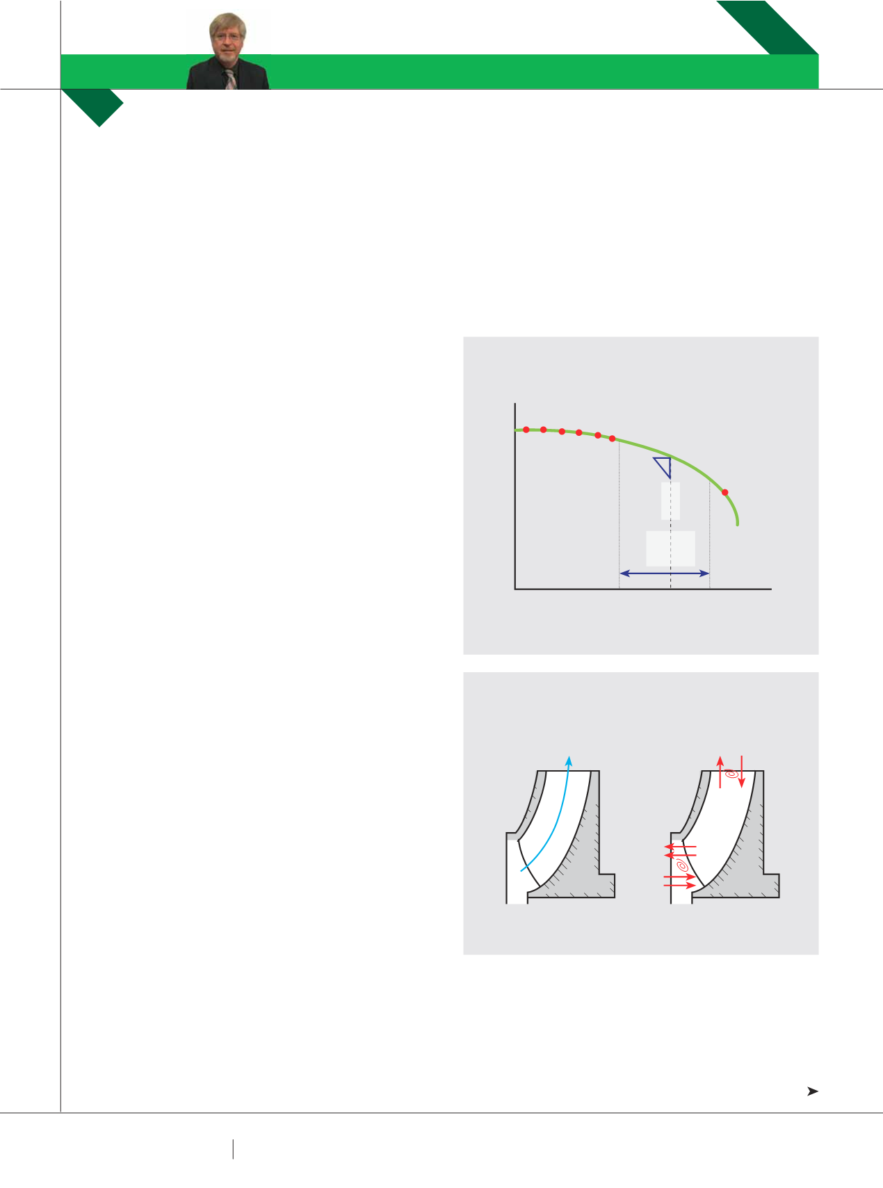
Instead of agonising about the best definition right
now, let us instead have a look at what happens inside a
centrifugal pump at various off design flows. See Fig 1.
Fig 1 is generalised but provides a convenient overview
of the symptoms associated with low flow operation issues
such as:
∫ Increased internal turbulence
∫ Recirculation
∫ Increased pressure fluctuations
∫ Increased vibration due to the above
∫ Increased axial thrust – depending on pump hydraulic
balance method
∫ Increased radial thrust; particularly with single volute casings
∫ Temperature rise due to high internal energy loss
∫ We will look at some of these in more detail.
UNDERSTANDING PUMP CURVES
#5: MINIMUM FLOW –
PART ONE
RON ASTALL
DISCUSSES WHAT HAPPENS INSIDE A CENTRIFUGAL PUMP AT LOW FLOWS AND HOW BEST TO
DETERMINE MINIMUM FLOW.
PUMP SCHOOL
RON ASTALL
FIG 1: HEAD VS. FLOW
FIG 2: FLOWDISTRIBUTION
FLOW
IDEAL FLOW
DISTRIBUTION
DISTORTED FLOW
REVERSAL VORTEXING
HEAD
HIGH TEMP RISE
LOW FLOW CAVITATION
REDUCED BEARING AND SEAL LIFE
COURTESY PIA AUSTRALIAN PUMP TECHNICAL HANDBOOK
REDUCED IMPELLER LIFE
SUCTION RECIRCULATION
DISCHARGE RECIRCULATION
CAVITATION DUE TO
LACK OF NPSHA
BEP
PREFERRED
SELECTION
ZONE
BEP
LOWFLOW