


 60 / 116

6 0
PLUMBING CONNECTION
AUTUMN 2015
INTERNAL TURBULENCE
The Best Efficiency Point (BEP) is where a centrifugal
pump works best. This is the flow the hydraulic passages in
pumps were designed for, where the fluid velocities most
closely match the geometries of the impeller and the casing,
where the pressure distribution around the impeller(s) is
symmetrical and where hydraulic passage entry and exit are
the smoothest.
Operating away from BEP moves the velocity profiles away
from this ideal, leading to compromised flow, inevitable
turbulence and recirculation. An excellent analogy is a
sailboat; with the sail being equivalent to the vanes of the
impeller. At BEP the sail is correctly angled to the wind. Away
from BEP the sail will flap or flutter. The further away from
BEP, the worse it gets.
Fig 2 shows a simplified representation of smooth flow
at BEP versus the sort of flow disturbances that occur
at reduced flow. It does not take much to realise that the
distorted flow and turbulence will become worse the further
away you get from BEP.
The degree of turbulence and associated vibration and
buffeting depends on the hydraulic design and on the
energy levels in the pump. The effects are generally worse
for impellers with relatively large entry diameters. In larger,
higher energy pumps, vortexing (recirculation) can be so
severe that cavitation like effects ensue. It is possible to get
quite intellectual about this and we could discuss here such
aspects as the influence of Suction Specific Speed (Nss)
and the theoretical onset of recirculation. For the sake of
simplicity these details will be left for a later article.
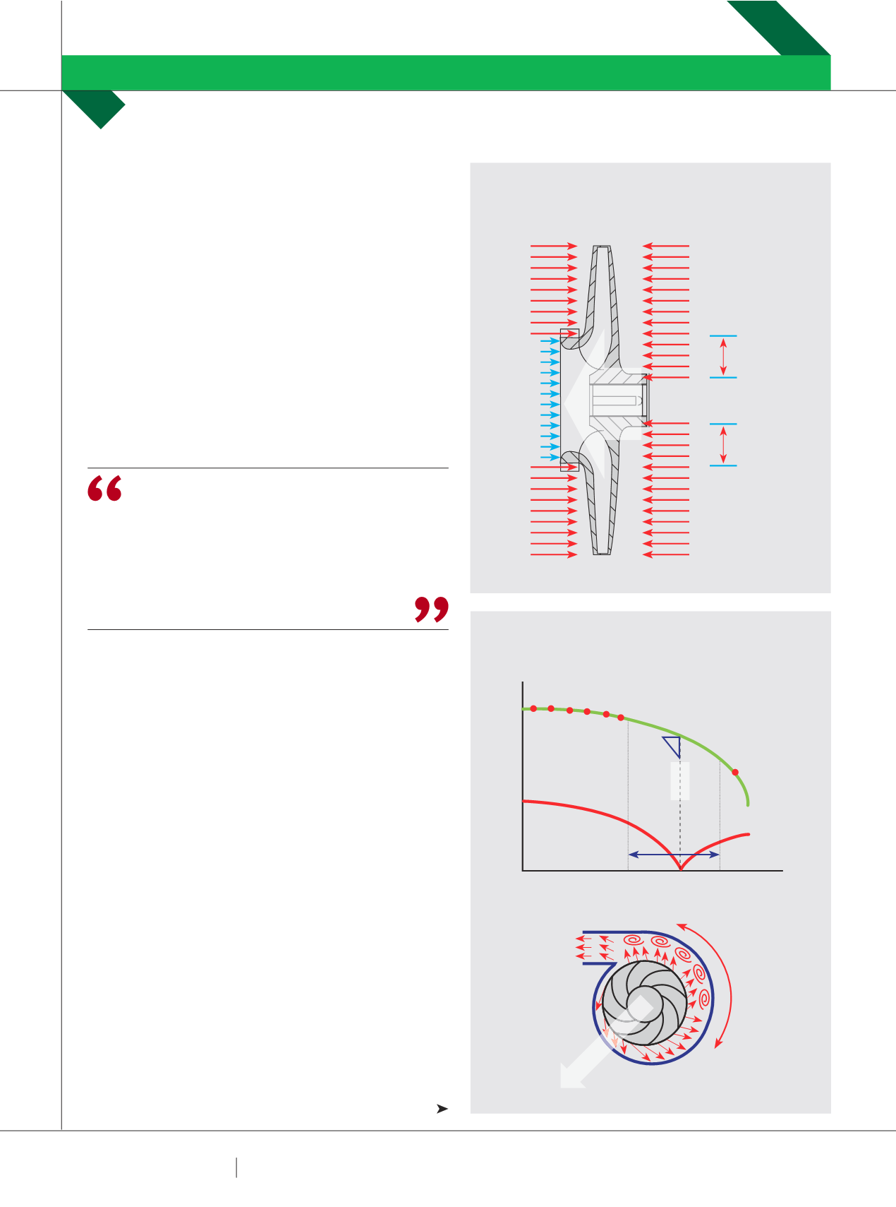
AXIAL THRUST
Hydraulically unbalanced impellers generate an axial
thrust that is proportional to the differential head. Refer
to Fig 3 for a simplified representation of this effect. At
reduced flow, the differential head will be higher and the
generated axial thrust will increase. In multistage pumps
this thrust is generally handled by a balance device that will
automatically compensate, or by having impellers facing
opposite ends of the pump.
THE DEGREE OF TURBULENCE
AND ASSOCIATED VIBRATION AND
BUFFETING DEPENDS ON THE
HYDRAULIC DESIGN AND ON THE
ENERGY LEVELS IN THE PUMP.
PUMP SCHOOL
RON ASTALL
FIG 4: SINGLE VOLUTE RADIAL THRUST
FIG 3: HYDRAULICALLY UNBALANCED IMPELLER
FLOW
HEAD
HIGH TEMP RISE
LOW FLOW CAVITATION
REDUCED BEARING AND SEAL LIFE
REDUCED IMPELLER LIFE
SUCTION RECIRCULATION
DISCHARGE RECIRCULATION
RADIALTHRUST
CAVITATION DUE TO
LACK OF NPSHA
BEP
AT LOW FLOW
RADIAL THRUST
H
I
G
H
E
R
A
V
E
R
A
G
E
P
R
E
S
S
U
R
E
UNBALANCED AREA
OUTLET PRESSURE
OUTLET PRESSURE
INLET PRESSURE
OUTLET PRESSURE
OUTLET PRESSURE
UNBALANCED AREA
AXIAL
THRUST