


 40 / 116

4 0
PLUMBING CONNECTION Summer 2017
HIGH RISE - LOWPRESSURE
A
s high rise buildings become
more prevalent and with ever
increasing heights, the push by
developers is to maximise floor space
for tenants. For services this results in
designs that call for smaller footprints
or better still, no plant rooms.
Conventionally, water is brought in
from mains to a basement plant room,
where pumping systems are installed
to adjust the pressures appropriately
to reach storage tanks
at the top levels of
the building. As water
is directed down
through the building to
each storey, pressure
reduction valves would
be incorporated in a
single stage process.
In the past, this was
sufficient for buildings
that were in the order of
20 – 25 storeys.
A 36 storey building
currently under
construction in Sydney
is pushing conventional
methodologies to its
limits, potentially creating
noisy pipes, cavitation and
reduced lifespan of the
hydraulic infrastructure.
The company contracted
to design the hydraulic system for the
building, Wood & Grieve Engineers,
had concerns about the suitability of
a traditional single-stage pressure
reduction system for 36 storeys.
Hydraulics principal with Wood
& Grieve, David Steblina says that
at 36 floors, the dynamic pressure
increase on valves to perform correctly
needed to be considered. As a result,
the company performed a number of
tests in a simulation to verify product
suitability and other options to meet
the requirements of the building.
“We had to find the balance between
cost and performance,” says David.
“The idea had to be cost effective,
but still reliable and robust enough to
deliver the performance needed. The
available products that we reviewed
were reported to perform, however
we weren’t convinced they would not
deteriorate and create noise when
subjected to these conditions. This
resulted in finding a different method
for regulating the pressure.”
The investigation, initiated and
led by Dr Houman Tamaddon, tested
pressure reduction valves in a dual-
stage configuration. A test rig was set
up to replicate the pressures likely to
be experienced in the building which
can potentially reach
1,800kPa.
In Houman’s report
on the test results, he
says that a “dual-stage
reduction concept
was developed for the
high pressure PRV
(pressure reduction
valve) station based
on a simple concept: if
the required pressure
reduction ratio from the
main riser pressure to
the point of use is more
than the optimal zone of
the pressure reduction
valves, implement a two-
stage, serial reduction
configuration.”
“To distribute the
pressure reduction evenly we
tested from 1800kPa down
to 450kPa in a two to one ratio,” says
Houman. “So it stepped down 1,800kPa
to 900kPa to 450kPa.
“The first step down is still too high
for most valves operating range, so a
modification was needed on the valve.
The second stage reduction would be
suitable for standard products.”
“Operating outside normal valve
range can lead to knock-on effects,”
says David. “Excessive pressure can put
the valves under serious stress which
can create whistling, cavitation and
reduced life spans.”
To develop a prototype to perform at
the necessary pressure ratings, Wood &
Grieve worked with Caleffi in Italy and All
Valve Industries to modify the design of
)RU SOXPEHUV ¿WWLQJ RXW KLJK ULVH EXLOGLQJV WKH EDWWOH RI LQFUHDVLQJ SUHVVXUH KDV EHHQ KDQGOHG ZLWK
SODQW URRPV EXW SUHPLXP ÀRRU VSDFH ZDUUDQWV D QHZ DSSURDFK
Deborah Andrich
LQYHVWLJDWHV
PRESSURE REDUCTION VALVES
Dr Houman
Tamaddon, Hydraulic
Project Engineer,
Wood & Grieve
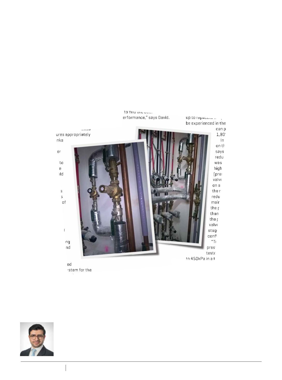
Left:
The hot water service is held in a
separate access cabinet – first stage
pressure reducing valve set in a bypass
arrangement.
Right:
On Level 1, a dual-
stage pressure reduction system meter
cupboard arrangement for even levels
incorporating first and second stage
pressure reduction.