Sizing and designing hot water recirculation systems
Unlocking the mysteries of heat transfer can be a confusing subject, Ken Sutherland writes. Especially when we must deal with heat transmission and the Plumbing Code of Australia, all in one sentence.
We know that hot water recirculation loops are used to cut down the wait time for hot water to reach our fixture and to reduce the amount of cold water going down the drain while we wait.
Heat transmission is a subject that the ordinary man in the street knows very little about. So, when you add that to pipework sizes, insulation thickness and water temperatures, the whole thing starts to get out of hand.
However, not to worry: the process itself is simple enough.
Find the heat lost through the insulation and replace this exact same amount of heat by circulating hot water.
Oh, and there are a few other incidentals, like the recirculation pump size, balancing valves, air valves, Pete’s plugs, insulation thicknesses and pipe sizing and a couple of unfamiliar terms associated with heat transmission.
So, let’s have a go at unlocking some of the mysteries.
The hot water loop piping is sized on loading units and index length, just like the cold water. It is not sized as a ring main. The return piping is sized on the circulation flow only. However, the Code applies different flows and velocities to those used for cold water. Large velocities in hot water can cause pipe erosion and other problems and are to be avoided. Hot water recirculation pipes are always insulated.
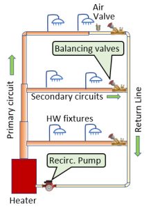
The circuits can be any shape or location. They can be vertical, or horizontal, or both as shown in the diagram.
The heater can also be anywhere; however, it is probably best to keep it at low level for ease of access, fuel delivery and, of course, hot water rises.
There can be any number of secondary circuits. A secondary circuit may be on every floor. The important thing is to join the secondary return line back to the main return line, and not to the main riser.
Heat loss
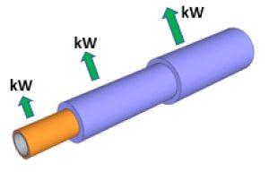
Even though the pipework is insulated, heat is still being lost. The amount of heat lost depends on:
- Pipe material
- Insulation resistance to heat conduction (“R-value”)
- Insulation and pipe thickness
- Pipe length
- Temperature difference between the hot water and the ambient air temperature. (The temperature gradient).
The heat loss is calculated in watts or kilowatts. The object is to calculate the total heat loss from everything in the recirculation pipe network.
Knowing this, we can calculate how many L/s of hot water we need to pump around the circuits to replace all the heat lost.
Heat transmission terms
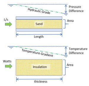
The best way to visualise heat flow, is to liken it to water flowing through a pipe filled with sand. The first problem term is ‘thermal conductivity’.
Thermal Conductivity
Thermal conductivity is a way of comparing different materials by measuring how many watts of heat can get through 1sqm of material of thickness 1m, if there is 1° temperature difference from one side to the other.
It’s like saying how many L/s can get through a one-square-metre, cross-sectional area pipe, one metre long, with one metre head loss.
R-Value
Heat is measured in watts. (Watts are actually joules/s where joules are an energy term, like calories in the imperial system).
To know how many L/s can get through a pipe, we need to know the inlet and outlet pressure, the area, and the length of the pipe. This allows us to calculate the hydraulic grade; we then use a formula to calculate the L/s.
It is the same with heat: We need to know the start temperature on the inside of the insulation and the end temperature on the outside of the insulation (the ambient or air temperature). We also need to know the area, and the length of the material the heat must go through, (insulation thickness). This allows us to calculate the temperature gradient (analogous to the hydraulic grade).
We then use a formula to calculate how many watts are getting through the insulation.
The R-Value is a measure of thermal resistance of a material of a particular thickness. When analogous to a sand-filled water pipe, it’s like calculating the resistance of the sand.
It’s a bit like Mannings ‘n’ in the Mannings fromula, or the Colebrooke-White ‘k’ in the Colebrooke-White formula for calculating pipe flow. But it’s spread out across the whole pipe and not just the wetted perimeter.
Anyway, it gives a figure that the Code uses to define what the R-Value of the pipe and insulation should be. The larger the value, the greater the thermal resistance.
This R-Value requirement is dependent on the hot water situation, i.e. circulating or not, associated with heaters or valves, pipework location inside or outside and the climate region.
The recirculation pump must be sized to push enough L/s around the network to replace the heat lost from the system. This introduces another interesting heat term, called the ‘specific heat’ of water.
Specific Heat
The specific heat is how many joules of energy it takes to heat one gram of water by 1°. (Turns out it takes a different amount of heat, to heat other substances one degree.)
Anyway, it takes about 4.2 kilojoules of energy to heat one kg of water by 1°. But it works both ways: if we lose 1° of heat from a kilogram of water, we lose 4.2 kilojoules. So pushing one L/s of water (1Kg/sec) we are losing 4.2 Kilojoules/sec.
Remember a joule/sec is a W, and a L weighs a kg, so if we push 1 L/s around the circuit, and we lose 1° heat, we have lost 4.2kW of heat.
There’s a simple formula that puts all this together. You can find it on the Internet now you know what to look for: Specific heat of water.
The interesting thing is: What about the hot water that is going to the fixtures anyway? And how does this affect things? Well, when fixtures downstream are drawing water already, there is not much wait time, so no need to recirculate.
Some systems work like this, i.e. the recirculation pump cuts in only when the temperature falls below a certain minimum.
However, for the rest of us, we design the recirculation pump assuming no fixtures are operating. However, in either case, here is the interesting bit: the recirculation flow must be added to the probable simultaneous flow to be able to calculate the final pipe size. But before we can calculate the recirculation flow to be added, we need to know the final pipe size.
Beautiful… a chicken and egg situation, or a Catch 22 (and a circular reference in coding terms).
So there is a bit of trial and error involved. The trial and error involves calculating the pipe sizes first, without the circulation flow. Then calculating the circulation flow required with these pipe sizes, and adding this flow to the design flow for the fixtures. Then upgrading certain pipe sizes to meet the velocity requirements, and the heat loss R-value.


