
Valley gutters: A performance-based perspective
Valley gutters are one of the least-defined components of gutter installation. Ken Sutherland aims to clear the air with this specific type of solution.
In the landscape of hydraulic design standards, valley gutters remain one of the least defined and most misunderstood components. Despite their widespread use, the guidance provided in AS/NZS 3500.3 Plumbing and Drainage Part 3: Stormwater Drainage is limited to a narrow set of conditions, leaving plumbers with few options when faced with real-world variability.
Valley gutters are found across a huge variety of roof designs in both residential and commercial construction, yet they often sit in a grey area when it comes to design responsibility.
Builders, roof plumbers and hydraulic engineers all encounter them, but there is rarely a clear consensus on who should dictate their size, fall or overflow provisions.
This uncertainty has led to widespread reliance on ‘rules of thumb’ or legacy practices that may not always comply with today’s codes or reflect the demands of modern buildings.
Part of the challenge is that valley gutters are rarely identical from one project to the next. Factors such as roof pitch, catchment size, rainfall intensity, gutter profile and the presence of obstructions can all affect how they perform. Unlike more prescriptive components such as downpipes or eaves gutters, valley gutters tend to be shaped by architectural considerations first, with hydraulic performance left to be addressed later, sometimes too late in the process.
Misjudging a valley gutter’s capacity can have serious consequences. Blockages, backflow and overflow events don’t just lead to water damage; they can also expose contractors to liability if the installation is shown to fall short of performance requirements. With extreme weather events becoming more frequent across Australia, ensuring roof drainage systems are resilient and well-documented has never been more important.
For these reasons, valley gutters deserve closer attention than they usually receive in design documents and on-site.
A clearer understanding of their limitations, the intent of AS/NZS 3500.3, and the principles of sound hydraulic design can help plumbers and designers move beyond guesswork and towards more reliable, compliant outcomes. This article explores the key considerations, supported by diagrams and worked examples, to help demystify valley gutter design in practice.
Limitations of the current standard
The only prescriptive guidance for valley gutters appears in Table 3.6.2 of AS/NZS 3500.3. This table assumes:
- A roof slope of 23.5°
- Side slope of 16.5°
- A maximum catchment area of 20m²
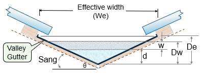
While the standard allows for varying rainfall intensities, it does not permit increasing the catchment area beyond 20m². Any configuration outside these parameters must be treated as a box gutter. However, the standard does not provide a method for designing box gutters with slopes steeper than 1 in 40 — a significant omission given that valley gutters often exceed grades of one in three.
The hydraulic transition zone
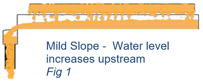
The reluctance to address steeper slopes stems from a critical hydraulic transition. At approximately 1 in 40, flow behaviour shifts from what is termed “mild” to “steep” slope conditions. This transition is analogous to an aircraft going through the sound barrier — but in our case it’s the water velocity going faster than the wave velocity.
- Mild slopes: Downstream conditions influence upstream water levels. A restriction downstream can cause the water level to back up and raise the upstream water level (Figure 2.1).
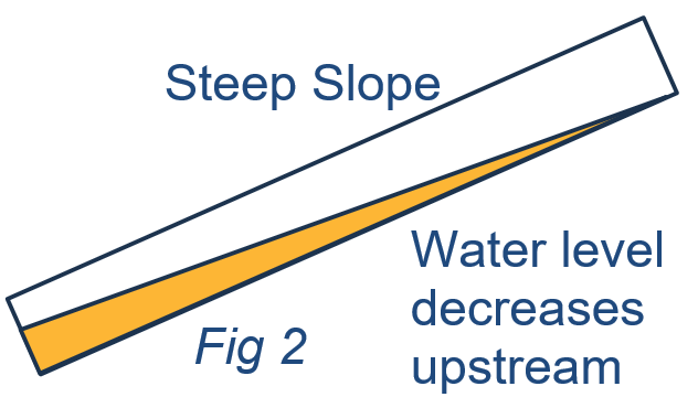
- Steep slopes: The upstream water level becomes independent of downstream conditions. Moving upstream, as the flow decreases, the upstream level also decreases but remains higher than the downstream water level.
(Figure 2.2).
In both cases, the water level upstream must always be higher than the water level downstream, otherwise the water would flow the other way. The outlet condition must also be a free outfall, an unobstructed exit without narrowing, redirection or orifice restriction. A downpipe pop or orifice does not qualify (Figure 3).
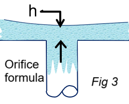
All the graphs in the plumbing code are based on the theory of having a free outfall. That is why all box gutters must drain to either a sump or a rainwater head to get a free outfall.
Hydraulic modelling requirements
Each slope condition requires a distinct hydraulic model. The design starts with a known depth at the outfall, and works back upstream to create a “backwater curve”.
- Mild slope: Water depth at the outfall is calculated using the critical depth formula.
- Steep slope: Depth approximates the Manning’s formula.
From the outfall, the water level is calculated in very small increments upstream to account for changing flows in each increment. This process calculates the water surface level at each increment.
Performance solutions and CFD
Given the limitations of Manning’s formula — which does not account for increasing flow, turbulence, or wave motion — performance-based design becomes essential. The 2025 revision of AS/NZS 3500.3 now explicitly permits the use of computational fluid dynamics (CFD) to develop performance solutions.
CFD modelling allows for:
- Variable slopes and catchment areas
- Accurate simulation of wave motion and turbulence
- Validation of freeboard and overflow conditions
Figure 4 presents a comparison between Manning’s formula and CFD outputs, using average flow conditions.
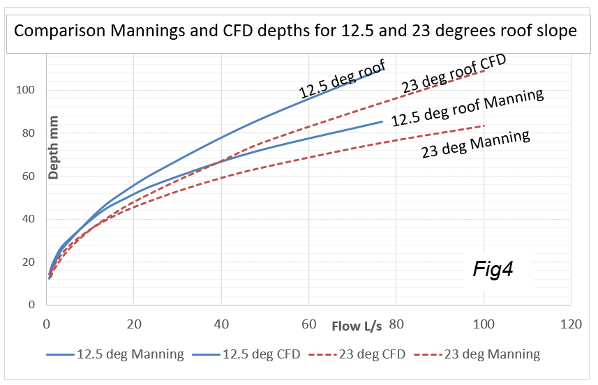
For low flows (under 10L/s), Manning’s formula may still provide acceptable approximations. However, this being an average depth, an allowance for wave motion and freeboard must be added.
Tools for designers
To assist designers in developing performance-based solutions for valley gutters, a CFD-based calculator is available on my website (roof-gutter-design.com.au/Valley-Gutters/ValleyGutter4.php).
This tool simulates flow conditions across a range of slopes, flows and catchment areas, providing a robust alternative to prescriptive design tables.