Understanding charged stormwater pipes and hydraulic grade design
Charged pipes are causing a lot of confusion and seem to have ‘fallen between the cracks’. They are not mentioned in any Plumbing Code, and some authorities are getting concerned and asking awkward questions. Ken Sutherland reports.
There are two types of charged pipes: Gravity pipes, as in stormwater drainage, where the pipes are designed to flow full, but not under pressure; and then there are pressure pipes, as in water supply.
A charged pipe is usually a stormwater (SW) pipe from a roof gutter that drops below ground, then rises again to empty into a tank.
In sewage design this is sometimes referred to as an ‘inverted siphon’.
In fact, there is one under the Brisbane River, where the sewer drops under the river and then rises to an access chamber on the other side.
However, a charged pipe is a stormwater pipe that remains full of water after the storm has finished. Hence the word ‘charged’. There is a small pressure left in the pipe.
This is where the cracks come in. It can’t be designed under the stormwater code AS/NZS 3500.3 Due to the pressure and it can’t be designed under the water supply Code AS/NZS 3500.1 because it is a stormwater pipe.
The water Code calculates head losses due to bends and fittings by the equivalent length method. That is, it lumps all the fittings together and allows an extra 50% pipe length to compensate for the head loss.
This is not suitable in our case. We must allow for the head loss due to each bend and fitting.
How do we do this?
We must go back to basics and design to the available hydraulic grade, accounting for all the possible head losses.
Pipelines have two forms of head (pressure) loss. One is from pipe friction. Smooth pipes, as in copper and plastic, have less friction than rough pipes, as in concrete and cast iron, etc.
The amount of friction is related to the roughness and is given a number. This number is used in the pipe design formulas.
There are many formulas, but the one used in the Code for stormwater drainage is the Colebrook-White formula. The number is called the roughness coefficient and is given the letter ‘k’. For plastic SW pipes k = 0.015mm.
Pipe design formulas can only calculate the loss through the pipe. The formula knows nothing about the bends and fittings. So now we must do a separate calculation to figure out this loss.
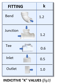
The loss through the bends and fittings is proportional to the fluid velocity, and to make life interesting it is also given the letter ‘k’. So be careful not to mix them up.
Each bend and fitting is given a k value. The equation is:
Head loss = k* V2/2g. Where V is the fluid velocity, and g is gravitational acceleration. The k values and design formulas can be found in this standard AS 2200-2006 Design charts for water supply and sewerage. The values can also be found on the Internet.
Calculating Pipe Sizes
To calculate pipe sizes, we need the Flow and the hydraulic grade. We then look up the Colebrook-White chart to find the pipe size.
The only difference for a charged pipe is the grade. The grade is not the pipe grade. The grade is called the Hydraulic Grade and can be used just like a pipe grade in the charts.
Finding the Hydraulic Grade
As our design flow may or may not occur once every 20 years, there are a lot of storms in between, so it will be easier to use the index length method as in the Water Supply Code.
The index length method calculates the hydraulic grade for the pipe length to the hydraulically worst case. This grade is then used for all pipes in the system.
STEP 1
Calculate the total available head from the underside of the lowest gutter to the obvert of the pipe at the tank. (See ‘D’ in Figure 2.)
STEP 2
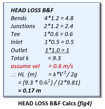
Calculate the head loss due to the bends and fittings (B&F). Sum the ‘k’ values for all the B&F (See Figures 3 & 4).
STEP 3
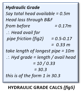
Calculate the hydraulic grade available for pipe friction (See Figure 2).
This is equal to L/H in Figure 2.
A typical calculation is shown in Figure 5.
STEP 4
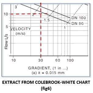
Look up the Colebrook-White chart for k=0.015 (See Figure 6) using the flow in each pipe section and the calculated hydraulic grade (See Figures 5 and 6).
The velocity was assumed in this calculation. This value may need to be changed to either increase or decrease the pipe HG.
For instance, using too large a velocity may make the HL through the B&F greater than the height drop from the gutter to the tank. This won’t work. Making the velocity too low may not suit the velocity calculated from the C-W chart. So, it is a ‘trial and error’ solution. (See Figure 6.)
You can also see from Figure 6 that the velocity is about 1.8m/s, so our assumed velocity of 0.6m/s was way too low and needs to be adjusted until the assumed velocity is near to the C-W chart velocity. Split the difference and see what happens.
You must also check that no pipe size is less than the upstream DP size.


