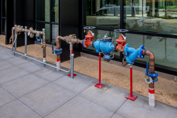
Best practice for installing backflow prevention devices on potable water systems
Peter McLennan dispels some myths surrounding the two main backflow prevention devices seen today: the reduced pressure zone device (RPZ) and the double check valve (DCV).
With the use and installation of backflow prevention devices being commonplace now since the mid-90s, you’d think the industry would have a good handle on the installation requirements and the hydraulic aspects of how they work.
However, based on some recent and recurring issues I’ve encountered, it seems that this may not be the case.
Hydraulics
Backflow prevention devices are very simple mechanical valves that stop the reversal of flow of drinking water. Each device is marked with the direction of flow as they can only operate in one direction.
The backflow prevention device uses force-closed, spring-loaded check modules that close when the incoming water pressure drops below the spring tension setting. The very fact that the incoming water has to overpower a spring means there will be a pressure loss across the check valve. The degree of this pressure loss will depend on the type of device installed.
The Double Check Valve (DCV) has two independently operating check valves within the same body. To comply with the Australian Standards the spring settings must exceed a differential across each check valve of 7Kpa. This means the minimum pressure drop across a DCV should be 14Kpa. In reality, 14Kpa is not achievable due to the tolerances in springs and the flow passages through a backflow preventer. Experience indicates that a DCV has a pressure drop in the vicinity of 25Kpa, but this also depends on the manufacturer and the age of the device as springs tend to go soft over time.
The Reduced Pressure Zone device (RPZ) also has two independently operating check valves within the same body but has a differential pressure relief valve that opens to atmosphere so that water will be drained from the device if a backflow incident occurs. To ensure the relief valve operates as it should, the spring tensions in the checks must be different enough to provide a safety margin, otherwise the device would continually drop water from the vent due to supply main pressure fluctuations. This extra safety comes at the expense of a higher pressure drop across the device as the spring tension on the first check must exceed 35Kpa and the tension on the second check must exceed 7Kpa. Again, experience shows that this 42Kpa is not achievable and the pressure drop across an RPZ is more likely to be above 65Kpa.
Protection of the drinking water comes at the expense of the available pressure, but a mechanical device is still often a better option than a complete break and re-pressurisation.
Installation guidelines
The RPZ is only approved for horizontal installation. This is because the vent to drain the water away must be the lowest point of the installation and this cannot be guaranteed in a vertical installation.
The DCV can be installed in both vertical and horizontal applications as long as there is adequate spacing around the device for maintenance, testing and repair.
The two questions most asked regarding the installation of a backflow preventer are as follows:
- Do I need to support the device?
- What size drain do I need under the RPZ?
The first is easy. It is good practice to support the device so that its weight doesn’t cause any strain on the pipe work. Use a commonsense approach and ensure the finished job is commensurate with the professional you are.
The second is much more difficult. All device manufacturers provide information on the discharge volumes that RPZs will dump at various pressures. Devices will dump water for a number of reasons. One is pressure fluctuations. This will cause the device to spit water from the relief vent and often will not cause more than a minor inconvenience. Another is the device will empty all the water from within the valve should a negative supply incident occur. This can be a large volume depending on the size of the device; 15mm may be a cup full, 250mm will be a bucket or more. The other reason is a massive failure whereby through either the head pressure within the piping system or a ring main feed, the device goes fully open and discharges continually at full back pressure.
This is where the drain size is critical and could mean the difference between an inconvenience and a large cleanup cost and potential insurance claim/litigation case. Your customer expects the designer and the installer to understand the operation and potential issues so ensure you know what the device manufacturer recommends for their device.
Ensure you read the installation instructions supplied with the valves or ask your supplier for some training. Ongoing skills based training and development can assist with minimising the chance of unexpected pain and suffering.

